| The clutch operation was extremely heavy and awkward as the
original modification when the engine went in was to use the clutch fork from the Healey
(Sunbeam Rapier) with the existing cable. This was done by cutting the Rover slave
cylinder off the bell housing and connecting the existing Healey components. God was that
clutch heavy! I snapped one cable and was on my way to stretching and breaking the
replacement when I thought enough is enough. |
| I looked around and phoned a few kit car specialists, Cobra
replicas, but they only had parts for Ford convertions. I searched through internet sites
looking for inspiration and found that people putting Rover V8 in Ford Capri's had a site
dedicated with convertion products and a link to someones website who had pictures of a
"remote" convertion. I nicked the idea and decided to make up
my own assembly. Mean while Han Kamp sent me some info on his convertion (non remote). First
I had to order all the replacement bits, a new bell housing, slave cylinder, clutch
fork etc. Most people doing this from scratch will have all the original Rover bits un
damaged. Then I found a master cylinder in a breakers yard off a Sherpa, I reasoned that
these had V8's as an option and the master would have the same throw as a SD1 master.
Again if you are using a SD1 donor use it's master. For the non remote as Han Kamp's is a
Nissan Bluebird has a two piece master, resevoir is connected to the plunger body by a
pipe not integrally mounted. |
| Main support bracket 1.This has to mounted first. It is attached to the
Brake servo using the existing 17mm nut (leave the washer behind the bracket) see fig 2
& 3.
2.Hydraulic Master with cable support. Attached to part 1 next using 13mm bolt and nut.
See fig 3
3.Remote actuator lever. Attached to part one and bottom edge sited inside lip of inner
wing rail. See fig 4. The pivot bolt has been secured from movement by rubber sealant. The
bottom hole is to locate with the master plunger and the top bolt is used to secure the
clutch cable. |
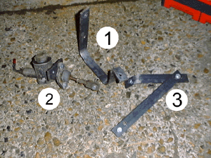 Fig 1 Fig 1 |
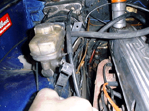 Fig 2 Fig 2 |
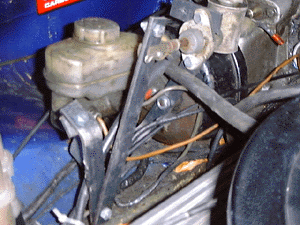 Fig 3 Fig 3 |
| I didn’t have the equipment to make a hole in the raised lip to mount
the bottom of the bracket with a bolt so a small weld makes it solid. |
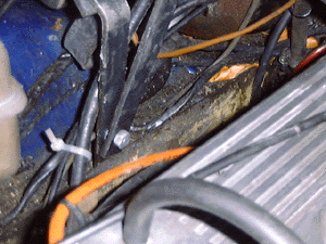 Fig 4 Fig 4 |
| This shows the original cable operating the clutch with the cut down
version (from the one I snapped) being measured up. |
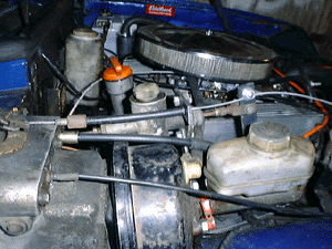 Fig 5 Fig 5 |
| A small piece of the metal bar I used to make the bracket is bolted to the
top of the master with a hole for the clutch cable to go through. When cutting the
original cable down to size remember to leave more of the Teflon sleeve than the rubber
and steel sleeve this goes through the plate to stop friction. |
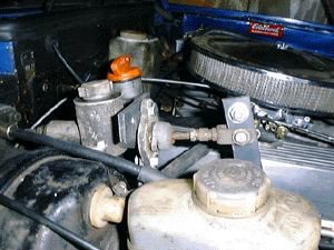 Fig 6 Fig 6 |
| The bracket as described above was still too flexible more support was
added during fitting and when I get a chance to take the photos I'll update this page
fully. |
|